Dr. Vadym Zayets
v.zayets(at)gmail.com
My Research and Inventions
click here to see all content |

Dr. Vadym Zayetsv.zayets(at)gmail.com |
|
|
IntroductionExperimental observation of transverse MO effectProperties of transverse MO effectOrigin of transverse MO effectTransverse EllipticityTwo contributions to transverse MO effectMagnetization-dependent optical lossCalculations of transverse MO effect in the case of multilayer structureOptical excitation of spin-polarized electrons utilizing transverse MOPlasmonsGiant Enhancement of Transverse MO effectHistory and Future |
Transverse Magneto-Optical effect
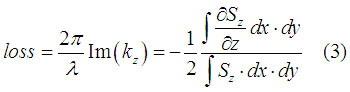
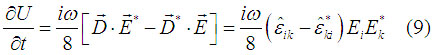
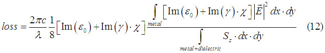
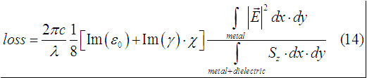
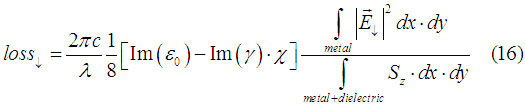
Magnetization-dependent optical lossThe expression, which described optical loss in the case of transverse MO, effect will be derived. Utilizing a few very general facts, the important properties of the effect are derived. Expression (14) can be applied to calculate and estimate the transverse MO effect for a variety of possible structure. It can be applied to plasmons, hybrids waveguides, slab and rib waveguides and more. Eqn.(14) is main result. This method may be used for calculations of the transverse MO effect in devices with complex shape. For the devices with less complex shape the usage of simple rigorous method is preferable.
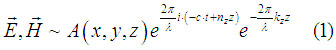
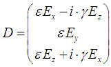
In the following we will calculate the magnetization-dependent loss for a very general structure, which contains a ferromagnetic metals and a transparent dielectric. The metals absorb the light and there is MO effect in the metal. The light along z direction. Let us to put as less limitations on the structure as possible. Only we assume that the light is confined inside the structure, so Because there is a metal inside the structure, light experience an optical loss, so there is a loss of energy, when the light propagates along z direction. The electrical and magnetic field of light can be described as
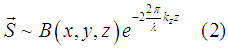
where A(x,y,z) is the slowly-varied function along z. nz is the effective refractive index and kz is the absorption coefficient. Since the wave is absorbed, the energy flow is decreasing along z axis and Poynting vector is
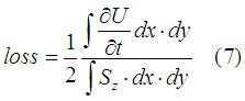
The optical loss can be calculated as
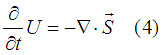
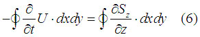
Poynting theorem reads
where U is the energy density of the electromagnetic wave. Integrating Exp.(4) we obtain
Since there is no flux when
Substituting (6) into (3) gives
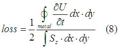
Since an energy dissipation is only inside metal, (7) is simplified to
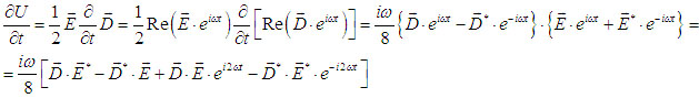
The energy dissipation in the metal is calculated as
Next we will use averaging over time, so parts, which have exp term, will become zero
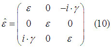
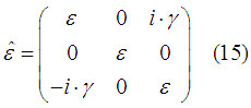
The permittivity tensor for metal is
and (9) is simplified as
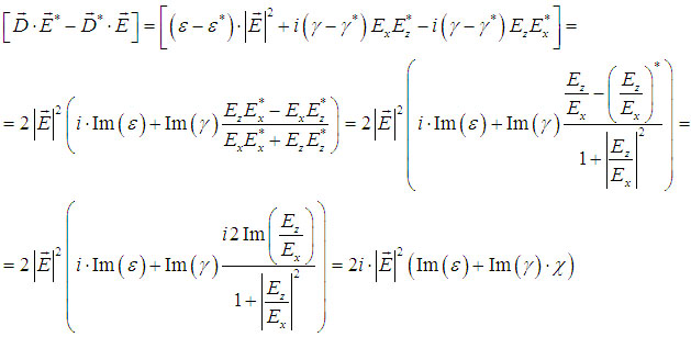
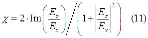
where
is the transverse ellipticity. Substituting (9) into (8), we have
in the case when the metal is single-layered and semi-infinite, (12) will be In the case when the magnetization of is reversed the permittivity tensor of the metal changes to
and optical loss will be
if the field distribution does not change
Exp. (17) describes bulk contribution to transverse MO effect. It is linearly proportional to the transverse ellipticity. The ratio of integrals in right part of (14) describes the interface contribution. Even it is more complicated, but it also is proportional to the transverse ellipticity.
|
I will try to answer your questions as soon as possible